Share
Pin
Tweet
Send
Share
Send
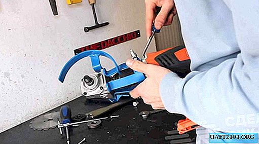
Here is the assembled structure:
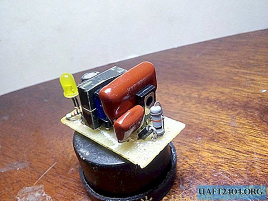
Pretty compact.
Main characteristics:
- Output voltage - 12 volts;
- Power - 5 watts;
- Wide range of supply voltages;
- Reliability.
Scheme
So, let's start with the device diagram. She is now in front of you.

The high-voltage part is a single-cycle generator built on the basis of a single transistor.
Parts List:
- VT1 - mje13001 (or more powerful mje13003);
- VD1 - 1N4007;
- VD2 - FR107;
- LED - LED of any color (I took yellow);
- R1 - 15 kOhm, 0.5-1 Watt (in order to increase the power of the circuit, I took 10 kOhm);
- R2 - 300 kOhm;
- R3 - 2.2 kOhm;
- R4 - 1.5 kOhm;
- C1 - 33 nF, 400 Volts;
- C2 - 10 nF, 1 kV (I did not find a capacitor per kilovolt, so I took it to 2 kV);
- C3 - 100 uF.
Resistor R1 limits the output current, R2 discharges the capacitor after disconnecting the circuit from the network, the same role for R3. On the parts VD1 C1, VD2 C3 assembled half-wave rectifiers.
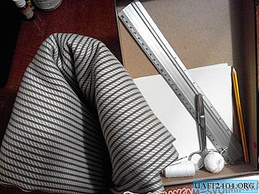
A suitable transformer can be found in old chargers. Carefully disassemble the core, rewind the old windings and proceed to winding new ones. The primary winding (it is also collector) consists of 200 turns of wire with a diameter of 0.08 - 0.1 mm. You can reel both manually and by a winding mechanism. The latter is useful in that you can see how many turns are already there.

(In the photo, the counter shows an incorrect value)
We wound the coiled coil for breaks.

We put insulation, one layer is enough, and in the same direction we wind 10 turns of wire of the same diameter, isolate it.

Now we take a thicker wire (0.5 mm) and wind the low-voltage winding with it. One turn is approximately equal to one Volt. I wound 14 turns so that there was a voltage margin.

We also apply a layer of electrical tape on the secondary winding.
Since the generator is single-cycle, a piece of office paper should be placed between the parts of the core. We assemble the transformer, fix the core with tape. Done!

Printed circuit board
Download board:
____2018-03-09_16-57-01.zip 19.16 Kb (downloads: 340)
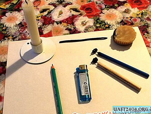
So, with the circuit and the role of its components figured out, now let's get down to manufacturing a printed circuit board. To do this, we need a 2x4 cm textolite and the printed circuit board itself.

We sand the copper part with fine-grained emery paper, then degrease it with alcohol. Next, transfer the drawing to the board using the LUT method.


If something has not survived, we finish with varnish.
We poison in a solution of hydrogen peroxide. I recommend this particular etching method, as it is the safest, fastest and most accessible.
At the end of the etching process, we take out our board, rinse it with water, wash the toner and varnish with acetone.

We solder tracks

The first to solder the VD2 diode in its place, do not forget about the polarity. The gray strip of the diode "looks up".

We solder the resistor R2 to the legs of the capacitor C2.

The remaining components are placed on the board in accordance with the following photos:


Networking
When you first turn on one of the power wires, it is necessary to connect a conventional 40-60 Watt incandescent lamp. This will protect your network from the effects of a possible short circuit in the circuit. If the lamp does not light during operation, then everything is normal and you can exclude it. Otherwise, the fault must be found and rectified. Often this is an excess of solder on the back of the board, which can shorten the tracks.
Conclusion
The reliability of the circuit lies in the fact that with a short circuit at the output of the circuit, all the energy is dissipated in the form of heat on the resistor R1.
The output power depends on the value of the resistor R1, the dimensions of the transformer and the diameter of the secondary winding, the voltage depends on the number of turns.
The setup does not need adjustment.
And on this my article came to an end. Good luck to everyone in the repetition!
Share
Pin
Tweet
Send
Share
Send