Share
Pin
Tweet
Send
Share
Send
The main materials:
- steel corner 20x20 mm;
- shaft on aluminum support SBR20;
- carriages on linear bearings under the SBR20 shaft - 12 pcs .;
- steel sheet 10 mm;
- corner 30x30 mm;
- long hairpin M10;
- steel sheet 3 mm;
- corner 40x40 mm;
- four-jaw turning chuck;
- bearings in the housing with paws -3 pcs .;
- shaft for bearings with paws;
- pulley on the shaft;
- electric motor with a pulley;
- drive belt;
- tool holder and cutters
- M8 bolts.
Lathe Making
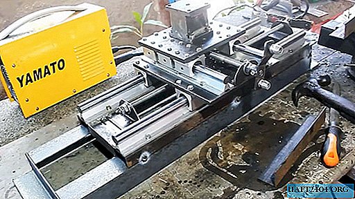
From the angle of 20x20 mm the frame of the machine is welded, as in the photo. The upper plane of the finished part must be sanded to be able to evenly attach the rest of the equipment.

2 longitudinal rails made of a shaft on the SBR20 aluminum support are screwed along the frame. They are mounted on 3 carriages on linear bearings.

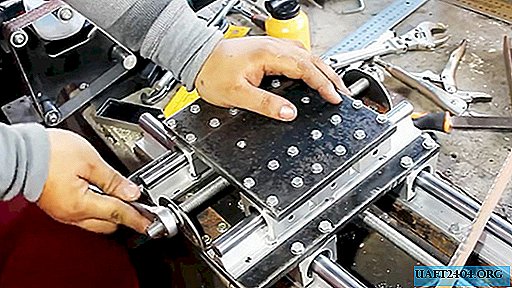
A base plate is cut out of 10 mm sheet steel, which will be fixed on carriages. It is screwed with 24 bolts of 4 per carriage.


Next, you need to fix the feed shaft, which will move the platform along the machine. For this, a long hairpin with a diameter of 10 mm is used. It is fixed at the ends of the machine to bolted supports from a turned corner 30x30 mm.

To attach the platform on the carriages to the shaft, it is necessary to make a protrusion on the back of its plate. To do this, the bracket is bent from a 3 mm steel strip. It must be screwed to the plate as in the photo.

Next, the bracket made is welded to the 3rd nut M10 screwed onto the feed shaft from the stud. Now, when the shaft rotates, the platform moves along the machine.

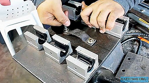
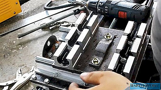
On the finished platform, 2 cross rails from the same shaft are fixed on the aluminum support SBR20. For each slide, 3 carriages are installed.

A steel plate 10 mm thick is screwed onto the carriages over 24 bolts.


For the transverse movement of the platform, the installation of a feed shaft is also required. It is made from the same M10 stud according to the same principle as the lower platform mechanism. To do this, 2 supports are made from a turned corner 30x30 mm and a bracket from a 3 mm strip, which is welded to the 3 M10 nuts on the shaft.

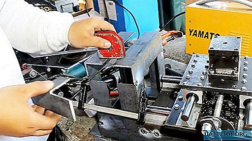
Next, you need to make the cube platform under the tool holder. Its upper and lower parts can be made of sheet steel 10 mm, and the sides of the sheet 3 mm. Since the load is exerted on this assembly, it should be reinforced with another 3 mm sheet steel insert. In the upper part of the obtained cube, a central hole is made in which the thread is cut. It is used to attach the factory tool holder.

The base of the tool holder with 4 bolts is screwed to a small platform of the machine.

Handles are mounted on the longitudinal and transverse feed shaft of the machine.
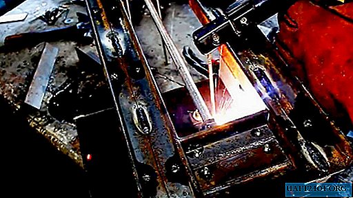
Around the base of the machine from a corner of 20x20 mm, a corner of 40x40 mm is welded. The longitudinal details of the new corner are made longer to get a base on the left for securing the spindle.
An angle of 40x40 mm is welded onto the base obtained, as in the photo. The resulting structure is strengthened by inserts, since it will have a strong deformation load.
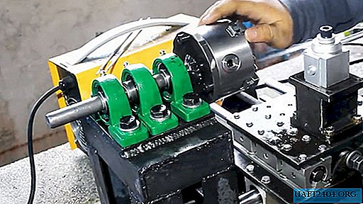
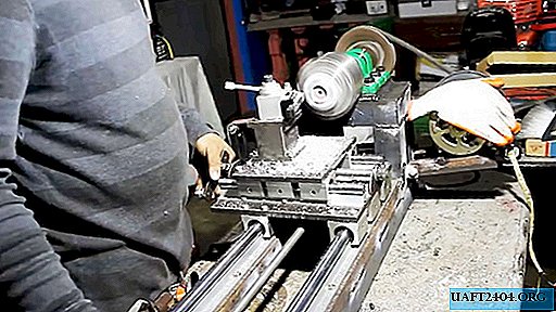
A platform of 10 mm sheet steel is welded on top of the resulting frame. 3 bearings are attached to it in a housing with tabs. A steel shaft is inserted into the bearings.

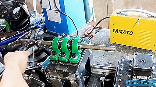
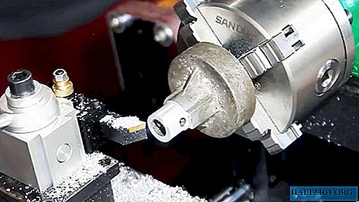
A circle corresponding to the diameter of the factory four-jaw chuck is cut out of 10 mm sheet steel. A large hole is made in its center corresponding to the diameter of the shaft. The fabricated part is mounted on a shaft mounted on bearings

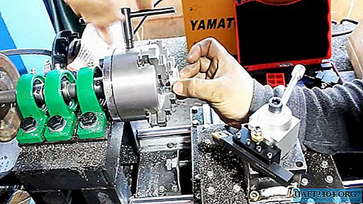
After installing and holding the four-jaw spindle on the shaft, it is necessary to press the cut circle to it and pull it with the cartridge with the help of 3 bolts. This allows you to balance the circle before welding it to the shaft.
Next, you need to remove the four-jaw spindle and cut off the excess part of the shaft along the line of the welded circle. The turning chuck is mounted back to its seat and clamped with 3 bolts.
A pulley is attached to the back of the shaft.

For an existing electric motor, a frame from a corner of 20x20 mm is brewed. A small pulley is mounted on the motor.

After that, pulling the belt between the pulleys, it is necessary to attach the engine to the base of the spindle shaft bearing platform. The frame of the electric motor must be made in such a way as to be able to adjust the tension of the belt after welding.

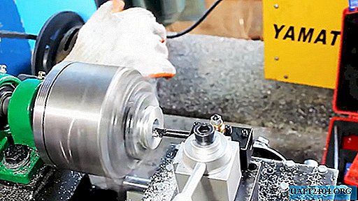
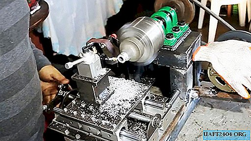
Having fixed the cutter in the tool holder of the machine, it is already possible to use it for its intended purpose. This design allows you to get the cutter to the circle on which the spindle is mounted to grind it, making it more accurate.


The resulting machine has the ability to upgrade, for example, the installation of the tailstock, which will allow you to perform more serious tasks. This is a rather expensive project, but it will cost less than a factory lathe.


Share
Pin
Tweet
Send
Share
Send