Share
Pin
Tweet
Send
Share
Send
There was a need to charge the car battery. You can take the LBP, but I use it in the workshop. I decided to assemble a charger for the garage.
Pondering an idea
Thinking over the design, I decided to stop on the alteration of the computer BP. Having studied information from the Internet, the task is quite simple. I found a power supply on an interesting chip 2003. It combines PWM and control the deviation of the main output voltage of the unit. Such is the block model. Most likely there are others, but I have this one.

I open and clean it from dust. The power supply must be operational.

Here is a close-up of a microcircuit. There is very little information about her. Searches closed on the circuit of the PSU itself and everything is almost clear.

Computer block diagram
The circuit has this initial form. Although the diagram shows 300 watts, my unit is assembled in the same way, the difference is visible in some components.

DIY alteration of the block into a charger
You need to delete the items marked in red. The resistor is yellow, change to 2.4 kOhm. Marked in blue, you need to replace it with a tuning resistor. The radiator with diodes was also fused off, without it it is convenient to search for components for removal. The marked voltages in green will be soldered to the error bypass board.

The photo clearly shows the deleted details. So far, I removed the capacitor C27 and the resistor R53. I solder the resistor back later, it is needed for uninterrupted charging. PS-ON wire soldered to minus to start the block.

I installed an additional inductor on the 12 volt line, removed it from the 5 volt line. The dual diode applied from the 5 volt line.

The group stabilization inductor freed from unnecessary windings. Wire cross sections, for my purposes, are enough.

To bypass the control of the deviation of the main stresses, I made a separate board. I made a board on such a breadboard. The board will be powered by 17 volts of duty. I will lower the voltage with the help of LM317, a 12 volt stabilizer is assembled. From 12 volts stabilizers on TL431 will be powered. I collected two stabilizers, at 5 and 3.3 volts. The missing resistor in the middle circuit is 130 ohms.

Such a board has turned out. Collected in half an hour.

I am soldering the wires according to our circuit. Blue and white wires, these are wires with a tuning resistor. When turned on, I configure the output to 14.3 volts.

I measure the resistance of the resistor, it turned out about 12 kOhm. I solder a combined resistor of two.

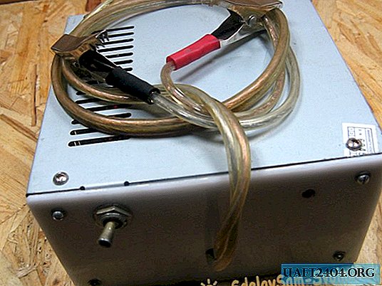
The output wires were taken by the first ones, only the “crocodiles” soldered to them.

I disconnect the network cable with the Soviet TV2-1 switch.

I fasten the power supply board to the standard holes. The plate was tied to a radiator. I installed a dual diode on the output, a simple protection against polarity reversal. You need to be careful, there is no protection against short circuit, I'll collect it later. I solder the output wires. The fan connected to the board a "snag" at 12 volts. The indicator LED is soldered to the charging output.

Forgot to mention. While the PSU board was being finalized, the case in which the board was originally was lost. Picked up a similar box. The benefit of them is in abundance.

The LED was fixed with hot glue.

Front panel made of plexiglass. I fasten the toggle switch to the panel, output the output wires and install the LED. The panel was screwed on. Dress, and screw the cap.
Total
Such a charger I did. For the garage is what you need. If you do not discharge the battery to the limit, the current is approximately 5 amperes. As you charge, the current drops.
Watch the detailed video
Share
Pin
Tweet
Send
Share
Send