Share
Pin
Tweet
Send
Share
Send
This chip, TDA2003, has found wide application in literally all types of audio systems - it can be found in portable speakers, in car radios, in computer speakers, in televisions and even in small music centers. Such popularity is due to a combination of several factors - it is cheap, economical in terms of current consumption, provides acceptable sound reproduction quality, and its power is enough to sound an entire room. The disadvantages include the fact that it is monophonic, that is, to reproduce a stereo signal, you need to collect two such amplifiers.
Scheme

The amplifier circuit is simple and does not contain any scarce parts. VR1 - a variable resistor with one group of contacts, serves to control the sound volume. It is advisable to use a resistor with a logarithmic characteristic for smooth adjustment, but a regular linear one will work. The HL1 LED is used to indicate that the amplifier is on and lights up immediately when a power is applied to the board. The supply voltage of this circuit lies within 8-18 volts. The most optimal option is 12 volts, so all electrolytic capacitors must be taken at a voltage of at least 16 volts, it is desirable to set more - 25 volts. The chip, especially when working at high volume, heats up significantly, so it needs at least a small radiator. Capacitor C5 is connected in series with the speaker and cuts off the constant component in the signal, so the constant voltage does not appear on the speaker, even if the microcircuit fails.

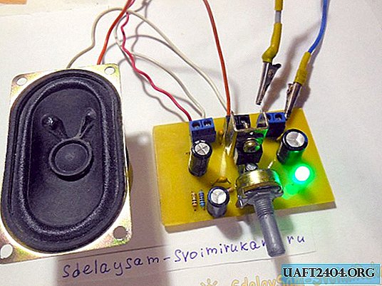
Amplifier assembly
usilitel-na-populjarnoj-mikrosheme-tda2003.zip 15.73 Kb (downloads: 469)
The whole circuit is assembled on a small printed circuit board measuring 45 x 55 mm, which can be done by the LUT method. The circuit board is completely ready for printing on a laser printer and does not require mirroring. After transferring the board, we put it in the etching solution and after etching we get the result as in the photo below.

Now all that remains is to erase the toner layer, drill holes and tin the tracks and you can proceed to sealing parts. First of all, small parts are installed - resistors and small capacitors, after them everything else. To connect the power, speaker and audio source wires, it is most convenient to use screw terminal blocks, as I did. In the last turn, a radiator is installed on the chip, you can use absolutely any one that is suitable for the board in size.


First launch and testing
To begin with, it is worth checking the correctness of installation, ringing adjacent tracks for a short circuit. If everything is assembled correctly, we supply power to the board by connecting a speaker, and leaving the signal input unconnected. In this case, it is advisable to turn the volume control to the minimum position so that the input of the microcircuit closes to ground. We supply power to the board, the LED should immediately light up. Now gently turn the volume control, you should hear a small crack in the speaker, because the input is now "hanging in the air." This means that the microcircuit is working - now you can send music to the input, for example, from a player, phone or computer. You can connect such an amplifier to any speakers with a resistance of 4-16 Ohms, the lower the speaker resistance, the greater the output power, respectively, and the heating of the chip. Have a nice build!
Share
Pin
Tweet
Send
Share
Send