Share
Pin
Tweet
Send
Share
Send
The ancient Greeks guessed the presence of an invisible force that sets certain objects in motion. However, the real dawn of this topic falls only on the period of industrialization of the 19th century. It was then that the famous scientist Michael Faraday discovered the phenomenon of electromagnetic induction, which explains the occurrence of an electric current in a magnetic field when a conductor moves in it. Today we suggest you to test this theory by experience.
The essence of the experiment is the manufacture of an electromechanical converter based on a DC motor that will rotate the magnets in the frame of the inductor. As a result of the excitation of magnetic fields and the appearance of electromagnetic EMF at the output, we obtain an electric current. The experience is also interesting in that the obtained voltage values will be greater than those expended on the operation of the engine. But first things first.
Materials - Tools
- DC motor at 3 V;
- Neodymium magnets square 10x8 mm;
- Steel rod with a section of 2-3 mm;
- Copper wire in varnished insulation;
- Pieces of plastic;
- 3.7 V battery;
- Copper wiring, heat shrink;
- Super glue.
Of the tools we need to work with: a soldering iron with solder, a lighter, a knife, pliers with pliers. A tester is needed for those who want to measure the output voltage on the converter.


We assemble an electromechanical voltage converter
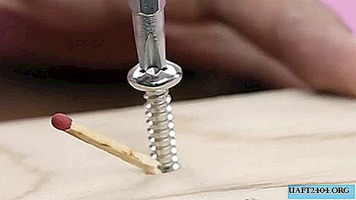
From the steel rod we make two small frames of the stator. We bend the contour with pliers, cut off the excess. The ends of the coils should also be bent (photo).


We connect the frames to the superglue, and put on the heat shrink in the middle. We warm it with a lighter, and in this way we get an insulated core of the coil.


For winding we use a thin copper wire in varnished insulation. It must be wound around the insulator area. The number of turns is 600.
Upon completion of the winding, we leave the two ends of the coil - the initial and final. We remove the insulation by burning it with a regular lighter. It will be a stator.


We put on a motor shaft a pair of guides made of plastic pieces for neodymium magnets on superglue. We place them on opposite sides of the shaft to increase the area of contact with the magnets.


We attach neodymium magnets to the shaft on superglue. Please note that they can connect only under the condition of different polarity. This will be the rotor of our converter.


We cut two strips of thin plastic into the size of the engine and frame. They can be slightly bent, warming the middle with a lighter.


Glue the strips to the engine body. Next, we fix the frame of the stator in such a way that its open ends, without touching the magnets, are placed in the center of the rotor.


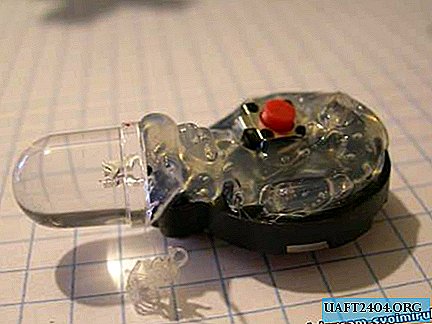
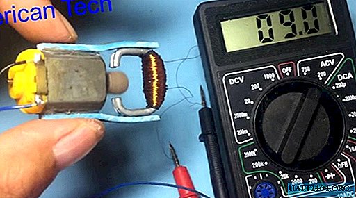
Our simplest micro-converter is ready. It remains to connect the engine, soldering its ends with contacts, and supplement the entire circuit with a battery. An ordinary lithium battery from a 3.7 V laptop is suitable as a supply battery.


Measurements by the tester show the output voltage, an order of magnitude higher than the input voltage, which means that such a circuit is quite working.
Conclusion
In fairness, it is worth noting that electromechanical converters are a thing of the past with the advent of electronic circuits and transistors. Today you can buy ready-made voltage boost modules that allow you to get high values of about 50 V from a regular battery of 3.2 -3.7 V. They are noiseless, compact and rational, because with their help you can power devices at 12 and 24 V, such like coolers and stepper motors with just one battery!
Share
Pin
Tweet
Send
Share
Send