Share
Pin
Tweet
Send
Share
Send
Device diagram
The scheme of switching on and off the load with one button is presented below. It is simple as a felt boot, does not contain scarce components and starts immediately. So the diagram:

Its key link is the popular NE555 timer chip. It is she who registers the keystroke and sets the output to either logical 1 or 0. Button S1 - any button to close without locking, because almost no current flows through it, there are practically no requirements for the button. I took the first Soviet one from the 60s.

Capacitor C1 and resistor R3 suppress the bounce of the button contacts, C1 is best used non-polar ceramic or film. LED1 indicates the status of the load - the LED is on, the load is on, off, off. Transistor T1 commutes the relay winding, here you can use any low-power transistor of the NPN structure, for example, BC547, KT3102, KT315, BC184, 2N4123. A diode standing parallel to the relay coil serves to suppress self-induction pulses that occur in the coil. You can use any low-power diode, for example, KD521, 1N4148. If the load consumes a small current, you can connect it directly to the circuit instead of the relay coil. In this case, it is worth putting the transistor more powerful, for example, KT817, and the diode can be excluded.
Materials

To build the circuit you will need:
- Chip NE555 - 1 pc.
- BC547 Transistor - 1 pc.
- Capacitor 1 uF -1 pc.
- Resistor 10 kOhm - 2 pcs.
- 100 kOhm resistor - 1 pc.
- 1 kOhm resistor - 2 pcs.
- Button without fixing - 1 pc.
- KD521 diode - 1 pc.
- 3v LED - 1 PC.
- Relay - 1 pc.
In addition, you need a soldering iron, flux, solder and the ability to assemble electronic circuits. Electronic components cost almost a penny and are sold at any radio parts store.
Device assembly
First of all, it is necessary to make a printed circuit board. It is performed by the LUT method, the file is attached to the article. It is not necessary to mirror before printing. The LUT method has been repeatedly described on the Internet; learning it is not so difficult. A few photos of the process:
Download board:
pechatnaya-plata.zip 5.04 Kb (downloads: 1001)


If there is no printer at hand, you can draw a printed circuit board with a marker or varnish, because it is quite small. After drilling the holes, the board must be tinned to prevent oxidation of the copper tracks.
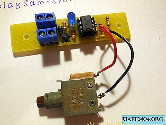
After making the board, you can begin to solder the parts into it. First, small components are soldered - resistors, diodes. After that, capacitors, microcircuits, and everything else. The wires can either be soldered directly to the board, or connected to the board using terminal blocks. I brought the power and OUT contacts for connecting the relay through the terminal blocks, and soldered the button directly to the board on a pair of wires.

Thus, this board can be integrated into any device, be it an amplifier, a home-made lamp, or anything else that requires turning on and off with one button without fixing. The network has many other similar circuits built on Soviet microcircuits, transistors, however, this circuit using the NE555 microcircuit has established itself as the simplest and most reliable at the same time.

The principle of operation is clearly shown in the video.
Share
Pin
Tweet
Send
Share
Send