Share
Pin
Tweet
Send
Share
Send
Similar emergency lights are used in many areas of human activity. The most striking example of the use of the circuit is electronic flashing beacons using official equipment (ambulance, police). Symmetric multivibrators based on the design described below can be found in other radio equipment, for example, in sound sirens and alarms. They are used in the simplest children's toys.
Device and principle of operation
The training multivibrator circuit, the phased assembly of which is described below, consists of two transistors, capacitors and LEDs. Additionally, depending on the voltage of the used power source, current-limiting resistors are added to the design.
The flasher works on two transistors according to the following principle. In the first phase, one of the transistors is in the open state, since current is supplied to its base from the symmetrical arm of the multivibrator. Due to this, one LED is lit and the opposite capacitor is charged. This completes the first phase of the cycle.
Further, when the capacitor is fully charged, no current flows through it. As a result, the transistor closes and the first LED goes out. Instead, a second flashes. This happens because the capacitor gives up the stored energy. In this case, the second transistor opens and the LED lights up. At the same time, the opposite capacitor is charged.
Next, the cycle is repeated according to the above algorithm.

Necessary materials and radio components
To assemble a classic 12 V LED multivibrator with your own hands, you will need the following radio components:
- KT361 transistors - 2 pieces (KT315 but you have to change the polarity of the power supply, capacitors and LEDs);
- electrolytic capacitors with a capacity of 47-50 microfarads and a nominal value of 16 V - 2 pieces;
- 3 V LEDs - 2 pieces (preferably multi-colored);
- 300 ohm resistors - 2 pieces;
- 27 kOhm resistors - 2 pieces;
- wires for connecting parts.

To distinguish KT361 transistors from the legendary KT315, just look at their markings. For those that are needed to assemble the multivibrator according to the above diagram, the letter is located in the middle of the case. At KT315 - in the corner. You can replace these details with more modern counterparts, for which it is enough to use special resources on the Internet. You can certainly use KT315, but in this case, the polarity of the power, capacitors, LEDs will need to be interchanged.
If there are no resistors with the indicated values at hand, then you can take a few pieces with less resistance. Combining them sequentially (as in the photographs), we obtain the required parameters. Note that with a power supply with a different voltage (9 V or 4.5 V), parts with a lower rating are needed.
Capacitors can be taken with a different capacity. This will directly affect the flashing frequency of the LEDs. The larger the capacity, the lower the switching frequency. The value of the capacitors must necessarily be greater than the voltage of the power source used.
Naturally, for the successful assembly of the symmetric multivibrator circuit, you will also need a minimal set for soldering.
Step-by-step multivibrator assembly
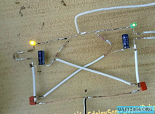
To begin with, it is recommended to collect all the necessary radio components and put them on the table as shown in the diagram. If soldering is carried out on the board, then this step can be skipped. When assembling a multivibrator by wall mounting, the sequence of actions will be as follows.


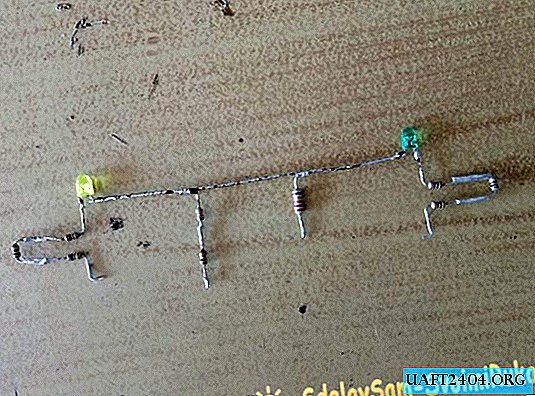

First, the LEDs are interconnected, and the main resistance of 27 kΩ is added to the circuit. This takes into account the polarity of the light sources. In classic LEDs, a negative conclusion is visible by visual inspection of the element - inside it is much wider than the positive. Between themselves it is the "minus" legs that are soldered. Resistors are mounted between the LEDs as shown in the photo.
Further, 300 ohm resistances are soldered to the positive terminals of the LEDs. They are needed in order to limit the current and save the elements from combustion.
Next is the turn of electrolytic capacitors. It is worth remembering that they also have positive and negative conclusions. The "minus" can usually be seen on the case - it is marked with a light stripe and corresponding symbols. At this stage of the assembly, we need positive conclusions - they are soldered to 300 Ohm resistances, as shown in the photo.
The most complex parts in this circuit (for beginner hams) are transistors. In order to simplify installation and not to confuse anything, it is recommended to immediately lay out the elements as shown in the photo. The transistor of the left shoulder of the multivibrator is drawn with the lettering up, and the right - down.


With this arrangement, the lower legs directed towards each other will be emitters. They must be interconnected. On the same site will be served with a plus sign.
Next, you need to connect the collectors of transistors with the positive terminals of the capacitors. For convenience, it is recommended to bend the middle legs of the parts accordingly (KT361 has collectors).
The last step is to connect the bases of the transistors with the negative terminals of the capacitors from the opposite arms of the multivibrator. Resistance, which was previously mounted in a circuit (27 kOhm), is also supplied to the soldering sites of these nodes. The bases of both transistors with this positioning will be on top, which will also facilitate the work with them.


Now it remains only to connect the wires from the power supply. A positive pin is soldered to the transistor emitter junction line, and a negative pin is between the LEDs. When you turn on the power supply, the multivibrator should immediately start working without any additional settings.
If the LEDs are not completely off when turned off, a small current-limiting resistor can be added to the beginning of the circuit. If the power supply is adjustable, it’s enough to reduce the voltage a little and everything will work.
Share
Pin
Tweet
Send
Share
Send