Share
Pin
Tweet
Send
Share
Send
However, a failed switching power supply can often be restored on its own.
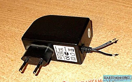
In the photo - a faulty switching power supply, model FC-2000. The output voltage of the PSU is 12 volts at a load of up to 2 A, which is quite enough to power one or two cameras. After two and a half years of work around the clock at its output, the voltage disappeared completely.

Opening the case of a faulty PSU, we find a board with parts installed on it - among them an electrolytic capacitor with a capacity of 10 to 47-68 microfarads and with an operating voltage of 400-450 volts; on its conclusions, even after a few minutes, a sufficiently large charge remains. Therefore, first of all, it is necessary to short-circuit its conclusions through a resistance of several kOhms and a power above 0.5W. It is not possible to short-circuit the terminals of the capacitor directly; this can damage it. In the photo in the red rectangle is precisely this detail. Since the bottom of the capacitor is swollen, we can say that the first malfunction is detected.

In addition to the filter of the rectifier filter mentioned above, components such as a fuse, a rectifier bridge (either a rectifier block or four separate diodes can be installed, as in the photo) and a transistor key - they are enclosed in green rectangles in the photo.

The operating voltage of the new capacitor must not be lower than that for which the replaceable one was designed. For testing, you can do with a smaller capacity, but to ensure the normal operation of the power supply, this parameter must be either the same or higher by one position (i.e., the capacitance from 33 μF can be increased to 47 μF).

Since in the described case the details of the high-voltage rectifier and the transistor turned out to be serviceable, we supply the mains voltage to its input. If you had to change the diodes or the transistor, the first switching on of the power supply should be done through a series-connected incandescent lamp with a power of 25-40 W - due to this, in the presence of hidden malfunctions, the magnitude of the current flowing through the primary power circuits will not be fatal.
We connect a voltmeter to the terminals - the voltage is within normal limits. However, having connected even a small load, the output voltage began to change stepwise from 5 to 11 volts, which indicates a malfunction of the stabilization circuits.

Further verification revealed a malfunction of another electrolytic capacitor installed in the circuit of the optocoupler PC 817.

Judging by the photo, the capacitor lost about 90% of its capacity.

After installing new parts, carefully wash off the flux residues (rosin, solder paste, etc.) with acetone or alcohol to avoid current leaks and possible breakdown and burning out of the board material.

Again, check the power supply. This time, an automotive lamp with a power of 21 W and a consumption current of about 2 amperes is connected to its conclusions - the power supply unit is designed for such a nominal operating current. As can be seen in the photo, he coped with his task "excellently", the light is on brightly, besides, it was possible to save 200-300 rubles and the time that would have been spent searching for a new switching power supply.
Share
Pin
Tweet
Send
Share
Send